Hello Friends, This is Mukesh from Learning Technology. I will tell you in today’s post, Determination of Shear Parameters of Soil by Triaxial Test in a very easy way.
Object of Experiment
The object is to determine the shear parameters of soil with the help of the triaxial compression apparatus by unconsolidated undrained tests without measurement of the pore pressure.
Standard Reference
IS 2720 (Part-13-1986)
Equipments
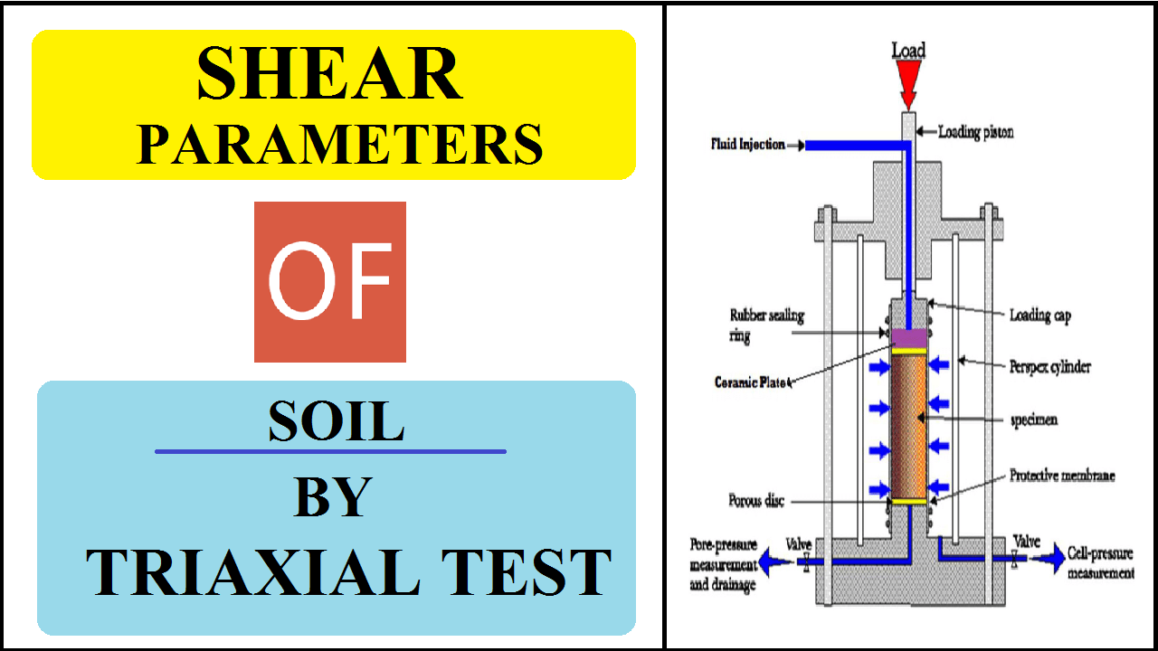
1. Triaxial cell
2. Pressure chamber fitted with valves with foot pump from applying and maintaining the desired fluid pressure in the cell.
3. Compression machine capable of applying axial compression to the specimen,
4. Dial gauge to measure axial compression
5. Rubber membranes
6. Membrane stretcher
7. ‘O’ ring – 2 numbers
8. Split moulds
9. Trimming knife
10. Balance
11. Stopwatch
Test Procedure
A) Preparation of undisturbed test specimen
1) Collect the sample in the sample tube
2) Extract soil sample from the sampling tube
3) Cut the soil cake at the desired length
4) Trim the sample to the correct size
5) Transfer the sample from the tube to a split mould
6) Grease the inside walls of the mould to avoid surface moisture loss
B) Preparation of remoulded test specimen
1) Remoulded sample may be prepared in a bigger mould by compacting the soil at the desired water content and dry density
2) Alternatively, remolded specimen may be prepared directly in the split mould. Apply grease to the mould to avoid surface driving during remolding the specimen. The remaining steps to be followed are the same as it is started for an undisturbed specimen.
C) Compression test
1. Place the specimen assembly centrally on the pedestal.
2. Admit the operating fluid in the cell, and raise its pressure to the desired value. Adjust the loading machine to bring the loading ram a short distance away from the set on the top cap of the specimen. Read the initial reading of the proving ring dial gauge. Adjust the loading machine further so that the loading ram comes just in contact with the seat on the top of the specimen. Note the initial reading of the dial gauge.
3. Apply the compressive force at a constant rate of axial compression, such that failure is produced in the sample with time. Take the readings of the load and deformation dial gauges simultaneously, plot the stress-strain curve. Continue the test until the maximum value of stress has been passed or until an axial strain of 20 % has been passed.
4. Unload the specimen and drain off the cell fluid. Dismantle the cell and take out the test specimen. Remove the rubber membrane and note down the mode of failure. Weigh the specimen. Keep samples for water content determination.
5. Repeat the test on three or more identical specimens under different cell pressures.
READ MORE
- Determination of Liquid Limit of Soil
- Determination of Consolidation Properties of Soil
- Specific Gravity of Soil Soild by Pycnometer
- Determination of Specific Gravity & Water Absorption of Aggregate
- Determination of Specific Gravity of Sand
- Determination of Fineness of Cement by Sieving
- Determination of Initial and Final Setting Time of Cement
Observations
i) Details of the soil specimens: Undisturbed / Remoulded soil
1. The initial diameter of the specimen (D0): …………… mm
2. Initial area (A0): …………… cm2
3. Initial moisture content: …………… %
4. The initial length of specimen (L0): …………… mm
5. The volume of specimen: ……………. cm3
6. Weight: …………… (gm)
ii) Undrained Triaxial test
A) Cell Pressure (σ3): ……………
B) Corrected area (A) = A0 / (1 – ε)
C) Proving ring dial gauge (LC) : …………….
| Dial gauge Reading (1) | Proving ring dial gauge reading (2) | Strain (ε) (%) (3) | Corrected area (4) | Deviator force (5) | Deviator stress σd = (σ1 – σ3) (6) |
From graph
Failure strain = ………………..
Deviator stress at failure = ………………..
|
Test No. (1) |
Cell Pressure (σ3) (2) | Deviator stress at failure σd = (σ1 – σ3) (3) |
σ1 at failure |
|
Test |
Sample 1 |
Sample 2 |
Sample 3 |
| Center [(σ1 + σ3) / 2] | |||
| Radius [(σ1 – σ3) / 2] |
Calculation
1. The deviator stress (σ1 – σ3) or principal stress difference at any stage of the test is determined by dividing the additional axial load by the corrected area.
2. Use a separate table for each test. Plot the deviator stress (σ1 – σ3) and strain (ε) and find maximum deviator stress (σ1 – σ3) and corresponding maximum strain.
3. The shear strength parameters are obtained from a plot of Mohr circles.
From Graph: The cohesion (C) = ………………..
The angle of internal friction (Φ) = ………………..
Remarks
Write your own experience from the experiment


