In this post, we are going to learn about the Glossary related to Design and Construction Of Pile Foundations.
Contents
- 1 Design and Construction Of Pile Foundations
- 1.0.0.0.1 1. Allowable Load
- 1.0.0.0.2 2. Anchor Pile
- 1.0.0.0.3 3. Batter Pile (Raker Pile)
- 1.0.0.0.4 4. Cut-off Level
- 1.0.0.0.5 5. Driven Cast In-situ Pile
- 1.0.0.0.6 6. Elastic Displacement
- 1.0.0.0.7 7. Factor of Safety
- 1.0.0.0.8 8. Follower Tube
- 1.0.0.0.9 9. Gross Displacement
- 1.0.0.0.10 10. Initial Load Test
- 1.0.0.0.11 11. Initial Test Pile
- 1.0.0.0.12 12. Load Bearing Pile
- 1.0.0.0.13 13. Net Displacement
- 1.0.0.0.14 14. Pile Spacing
- 1.0.0.0.15 15. Routine Test Pile
- 1.0.0.0.16 16. Safe Load
- 1.0.0.0.17 17. Ultimate Load Capacity
- 1.0.0.0.18 18. Working Load
- 1.0.0.0.19 19. Working Pile
Design and Construction Of Pile Foundations
1. Allowable Load
The load which may be applied to a pile after taking into account its ultimate load capacity, group effect, the allowable settlement, negative skin friction and other relevant loading conditions including reversal of loads, if any.
2. Anchor Pile
An anchor pile means a pile meant for resisting pull or uplift forces.
3. Batter Pile (Raker Pile)
The pile is installed at an angle to the vertical using temporary casing or permanent liner. Raker piles are normally provided where vertical piles cannot resist the applied horizontal forces. Generally, the rake will be limited to 1 horizontal to 6 vertical. In the preliminary design, the load on a raker pile is generally considered to be axial. The distribution of load between raker and vertical piles in a group may be determined by graphical or analytical methods. Where necessary, due consideration should be made for secondary bending induced as a result of the pile cap movement, particularly when the cap is rigid. Free-standing raker piles are subjected to bending moments due to their own weight or external forces from other causes.
Raker piles, embedded in fill or consolidating deposits, may become laterally loaded owing to the settlement of the surrounding soil. In consolidating clay, special precautions like provision of the permanent casing should be taken for raker piles.
- STACKING AND STORAGE OF MATERIALS
- Design and Construction Of Pile Foundations
- Evolution of Retaining Structures
- Glossary Relating To Bitumen And Tar
- Aluminium Formwork Refurbishment
- Safety For Hydraulic Tensioning Jacks
- Methodology of Post Tensioning Work
- Properties of Prestressing HT Strand
- Losses in Pre Stress due to Elastic Shortening
- Jack Pressure for Single and Multi Pull Stressing
- Elongation & Modified Elongation in Prestressing
- Prestressing Materials Management at Site
- Prestressing : Definitions | Advantage | Application
- Slipform – Slipform Planning at Site
- Labour Productivity Norms in Slipform
- Dismantling Procedure of Slipform
- Slipform Reinforcement Schedule Planning
- Assembly of Stair Tower for Slipform
- Assembling Procedure of Tapering Slipform
- Assembling Procedure of Straight Slipform
- Classification Of Slip Form Work
- Design Considerations of SlipForm
- Evolution of Slip Form Now a Days
- Measure Horizontal Distance Using AutoLevel
4. Cut-off Level
It is the level where a pile is cut-off to support the pile caps or beams or any other structural components at that level.
5. Driven Cast In-situ Pile
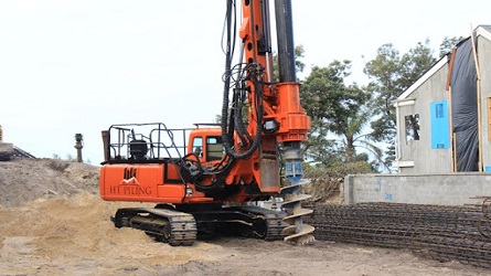
A pile formed within the ground by driving a casing of uniform diameter or a device to provide an enlarged base and subsequently filling the hole with reinforced concrete. For displacing the subsoil the casing is driven with a plug or a shoe at the bottom. When the casing is left permanently in the ground it is termed as the cased pile and when the casing is taken out it is termed as the uncased pile. The steel casing tube is tamped during its extraction to ensure proper compaction of concrete.
6. Elastic Displacement
This is the magnitude of displacement of the pile head during rebound on the removal of a given test load. This comprises two components :
a) Elastic displacement of the soil participating in the load transfer, and
b) Elastic displacement of the pile shaft.
7. Factor of Safety
It is the ratio of the ultimate load capacity of a pile to the safe load on the pile. The factor of safety should be chosen after considering,
a) the reliability of the calculated value of ultimate load capacity of a pile,
b) the types of the superstructure and the type of loading, and
c) allowable total/differential settlement of the structure.
- Bulking OF Fine Aggregates
- Concrete Cube Samples Taken for Different Volume
- Grades of Concrete as per IS 456 : 2000
- Flowchart For Aluform Work At Site
- Dismantling Process of Aluminium Formwork
- Assembling Process of Aluminium Formwork
- Dismantling Of Slab Aluminium Formwork
- Dismantling Of Wall Column & Beam Formwork
- Aluminium Formwork Concreting Process
- Assembling of Wall Aluminium Formworks
- Assembly Process of Aluminium Formwork
- Aluminium Formwork Worksite Management
- What is 1.54 in Concrete
- De Shuttering Period as per IS 456
- Grade Of Concrete And Its Cement, Sand And Aggregate Ratio
- Derivation Of (d²/162) – Unit Weight Of Bar
- Volume Of Different Shapes
8. Follower Tube
A tube that is used following the main casing tube when an adequate set is not obtained with the main casing tube and it requires to be extended further. The inner diameter of the follower tube should be the same as the inner diameter of the casing. The follower tube should be water-tight when driven in water-bearing strata.
9. Gross Displacement
The total movement of the pile top under a given load.
10. Initial Load Test
A test pile is tested to determine the load-carrying capacity of the pile by loading either to its ultimate load or to twice the estimated safe load.
11. Initial Test Pile
One or more piles, which are not working for piles, may be installed if required to assess the load-carrying capacity of a pile. These piles are tested either to their ultimate load capacity or to twice the estimated safe load.
12. Load Bearing Pile
A pile formed in the ground for transmitting a load of a structure to the soil by the resistance developed at its tip and/or along its surface. It may be formed either vertically or at an inclination (batter pile) and may be required to resist uplift forces.
If the pile supports the load primarily by resistance developed at the pile tip or base it is called ‘End bearing pile’ and, if primarily by friction along its surface, then ‘Friction pile’.
13. Net Displacement
The net vertical movement of the pile top after the pile has been subjected to a test load and subsequently released.
14. Pile Spacing
The spacing of piles means the center-to-center distance between adjacent piles. The minimum center-to-center spacing of piles is considered from three aspects, namely,
a) practical aspects of installing the piles,
b) diameter of the pile, and
c) nature of the load transfer to the soil and possible reduction in the load capacity of piles group.
NOTE — In the case of piles of non-circular cross-section, the diameter of the circumscribing circle shall be adopted.
In the case of piles founded on hard stratum and deriving their capacity mainly from end-bearing, the minimum spacing shall be 2.5 times the diameter of the circumscribing circle corresponding to the cross-section of the pile shaft. In the case of piles resting on a rock, the spacing of two times the said diameter may be adopted.
Piles deriving their load-carrying capacity mainly from friction shall be spaced sufficiently apart to ensure that the zones of soils from which the piles derive their support do not overlap to such an extent that their bearing values are reduced. Generally, the spacing in such cases shall not be less than 3 times the diameter of the shaft.
15. Routine Test Pile
A pile that is selected for load testing may form a working pile itself if subjected to routine load test up to not more than 1.5 times the safe load.
16. Safe Load
It is the load derived by applying a factor of safety on the ultimate load capacity of the pile or as determined from the load test.
17. Ultimate Load Capacity
The maximum load which a pile can carry before failure, that is, when the founding strata fail by shear as evidenced from the load settlement curve or the pile fails as a structural member.
The load-carrying capacity of a pile depends on the properties of the soil in which it is embedded. Axial load from a pile is normally transmitted to the soil through skin friction along the shaft and end-bearing at its tip. A horizontal load on a vertical pile is transmitted to the soil primarily by horizontal subgrade reaction generated in the upper part of the shaft. The lateral load capacity of a single pile depends on the soil reaction developed and the structural capacity of the shaft under bending. It would be essential to investigate the lateral load capacity of the pile using appropriate values of horizontal subgrade modulus of the soil.
The ultimate load capacity of a pile should be estimated by means of static formula based on soil test results. Pile capacity should preferably be confirmed by initial load tests [see IS 2911 (Part 4)]. The settlement of pile obtained at a safe load/working load from load-test results on a single pile shall not be directly used for estimating the settlement of a structure. The settlement may be determined on the basis of subsoil data and loading details of the structure as a whole using the principles of soil mechanics.
18. Working Load
The load assigned to a pile as per design.
19. Working Pile
A pile forming part of the foundation system of a given structure.
Source – IS 2911 (Part1/Sec1) : 2010
I hope you find this information useful. If there is something that I have missed or I do not know, you can comment and tell me which I will try to rectify as soon as possible.
If you have liked this post of mine, then use the social link given below and share it among your friends on social media. Thanks
SHARE THIS POST, IF YOU LIKE IT !!
Padhega India Tab Hi Badhega India | पढ़ेगा इंडिया तब ही बढ़ेगा इंडिया

Good Info