In this post, we will discuss the Evolution of Retaining Structures which contains its Definition, Types of Retaining Structures and Few Terminology related to Retaining Structures.
Contents
- 1 Evolution of Retaining Structures
- 2 Definition
- 3 Types of Retaining Structures
- 3.1 Cantilevered Retaining Walls
- 3.2 Types of Cantilevered Retaining Walls Include :
- 3.3 1. Masonry or Concrete Walls
- 3.4 2. Counterfort Retaining Walls
- 3.5 3. Buttress Retaining Walls
- 3.6 4. Gravity Retaining Walls
- 3.7 5. Stacked and Mortar-Bonded Stone, Rubble, or Rock Walls
- 3.8 6. Gabion or Crib Walls
- 3.9 7. Wood Retaining Walls
- 3.10 8. Tilt-up Concrete Retaining Walls
- 3.11 8. Segmental Retaining Walls (SRWs)
- 3.12 9. Bridge Abutments
- 3.13 10. Sheet Pile and Bulkhead Walls
- 3.14 11. Restrained (Non-yielding) Retaining Walls
- 3.15 12. Anchored (tieback) Walls
- 4 FEW TERMS & THEIR MEANING
- 5 Cantilevered Retaining Wall Terminology
Evolution of Retaining Structures
Definition
A retaining wall is any constructed wall that restrains soil or other material at locations having an abrupt change in elevation.
Types of Retaining Structures
There are many types of structures used to retain soil and other materials. Listed below are the types of earth retaining structures generally used today. The design of these will be discussed in later chapters.
Cantilevered Retaining Walls
These walls which retain earth by a wall cantilevering up from a footing are the most common type of retaining walls in use today. These walls are classified as “yielding” as they are free to rotate (about the foundation) because of the lack of any lateral restraint.
Cantilevered retaining walls are generally made of masonry or concrete, or both, but can also take other forms as will be described.
Types of Cantilevered Retaining Walls Include :
1. Masonry or Concrete Walls
The stem of a masonry wall is usually constructed of either 8” or 12” deep concrete masonry block units. The cells are partially or solid grouted, and are vertically reinforced. An eight-inch block is generally adequate to retain up to about six feet, and a twelve-inch block up to ten to twelve feet.
The stems of a concrete wall must be formed and can be tapered for the economy, usually with the taper on the inside (earth side) to present a vertical exposed face.
Hybrid walls, with both concrete and masonry, can also be constructed using formed concrete at the base, where higher strength is required, then changing to masonry higher up the wall. A variation for masonry cantilever walls uses spaced vertical pilasters (usually of square masonry units) with in-filled walls of lesser thickness, usually 6″ masonry. The pilasters cantilever up from the footing and are usually spaced from four to eight feet on center. These walls are usually used where lower walls are needed – under about six feet high.
- Bulking OF Fine Aggregates
- Concrete Cube Samples Taken for Different Volume
- Grades of Concrete as per IS 456 : 2000
- Flowchart For Aluform Work At Site
- Dismantling Process of Aluminium Formwork
- Assembling Process of Aluminium Formwork
- Dismantling Of Slab Aluminium Formwork
- Dismantling Of Wall Column & Beam Formwork
- Aluminium Formwork Concreting Process
- Assembling of Wall Aluminium Formworks
- Assembly Process of Aluminium Formwork
- Aluminium Formwork Worksite Management
- What is 1.54 in Concrete
- De Shuttering Period as per IS 456
- Grade Of Concrete And Its Cement, Sand And Aggregate Ratio
- Derivation Of (d²/162) – Unit Weight Of Bar
- Volume Of Different Shapes
2. Counterfort Retaining Walls
Counterfort cantilevered retaining walls incorporate wing walls projecting upward from the heel of the footing into the stem. The thickness of the stem between counterforts is thinner (than for cantilevered walls) and spans horizontally, as a beam, between the counterfort (wing) walls. The counterforts act as cantilevered elements and are structurally efficient because the counterforts are tapered down to a wider (deeper) base at the heel where moments are higher. The high cost of forming the counterforts and the infill stem walls make such walls usually not practical for walls less than about 16 feet high. See Figure.
3. Buttress Retaining Walls
These are similar to counterfort walls, but the wings project from the outside face of the wall. Such walls are generally used in those cases where property line limitations on the earth retention side do not allow space for the large heel of a traditional cantilevered retaining wall.
4. Gravity Retaining Walls
This type of wall depends upon the dead load mass of the wall for stability rather than cantilevering from a foundation.
5. Stacked and Mortar-Bonded Stone, Rubble, or Rock Walls
These are usually gravity walls relegated to landscaping features with retaining less than about four feet high. Engineering for such walls is limited, or none at all, and rules-of-thumb prevail (such as a retained height, not more than two or three times the base width). Higher walls need engineering to evaluate overturning, sliding, soil bearing and to verify that flexural tension does not exist within the wall (or only as allowed by code for material used) because these walls are generally unreinforced.
6. Gabion or Crib Walls
A gabion wall is a type of gravity wall whereby stones or rubble are placed within wire fabric baskets. Crib walls are a variation of the gabion method whereby mostly steel bins are filled with stone or rubble. Another variation is to stack a grillage of timbers and fill the interior with earth or rubble. Precast concrete crib walls are also widely used.
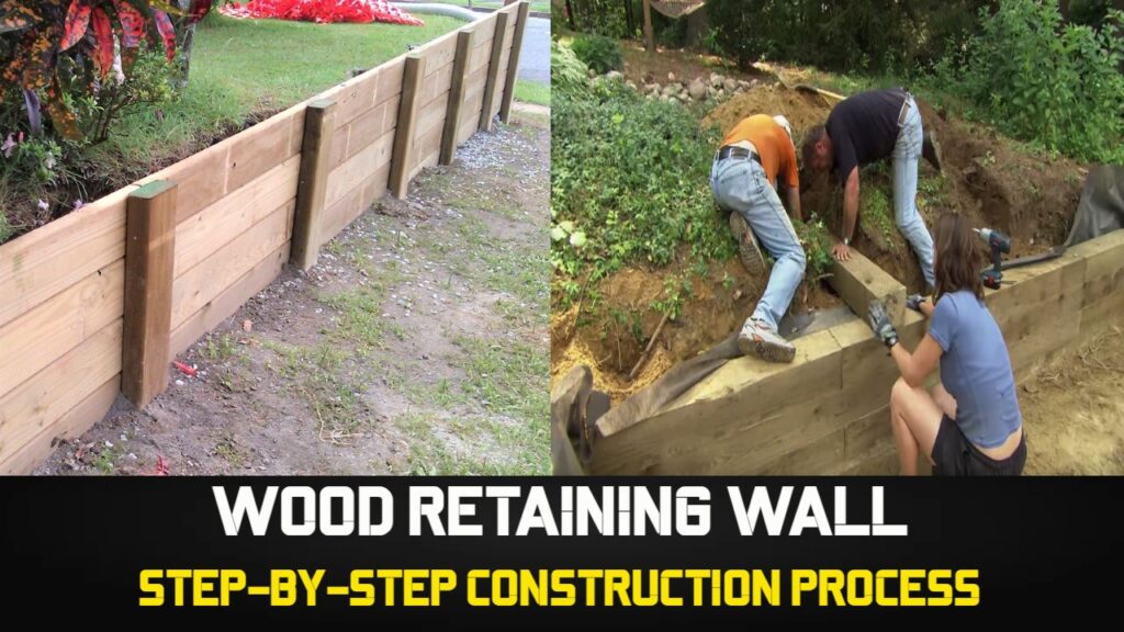
7. Wood Retaining Walls
Wood is commonly used for low height retaining walls. Wood retaining walls usually consist of laterally spaced wood posts embedded into the soil, preferably into a drilled hole with the posts encased in lean concrete. Horizontal planks span between the upward cantilevering posts. Pressure-treated wood is used, but even with treatment deterioration is a disadvantage, and wood walls are generally limited to low walls because height is limited by size and strength of the posts. Railroad ties are also commonly used for both posts and lagging.
- STACKING AND STORAGE OF MATERIALS
- Design and Construction Of Pile Foundations
- Evolution of Retaining Structures
- Glossary Relating To Bitumen And Tar
- Aluminium Formwork Refurbishment
- Safety For Hydraulic Tensioning Jacks
- Methodology of Post Tensioning Work
- Properties of Prestressing HT Strand
- Losses in Pre Stress due to Elastic Shortening
- Jack Pressure for Single and Multi Pull Stressing
- Elongation & Modified Elongation in Prestressing
- Prestressing Materials Management at Site
- Prestressing : Definitions | Advantage | Application
- Slipform – Slipform Planning at Site
- Labour Productivity Norms in Slipform
- Dismantling Procedure of Slipform
- Slipform Reinforcement Schedule Planning
- Assembly of Stair Tower for Slipform
- Assembling Procedure of Tapering Slipform
- Assembling Procedure of Straight Slipform
- Classification Of Slip Form Work
- Design Considerations of SlipForm
- Evolution of Slip Form Now a Days
- Measure Horizontal Distance Using AutoLevel
8. Tilt-up Concrete Retaining Walls
Tilt-up concrete construction has been successfully used for retaining walls, either cantilevered or restrained at the top. These site-cast panels are set on concrete pads at panel ends, with the reinforcing projecting out from the bottom. A continuous concrete footing is then cast under the wall to complete the construction. Tilt-up walls are economical for higher walls, but sufficient space is needed to cast the panels.
8. Segmental Retaining Walls (SRWs)
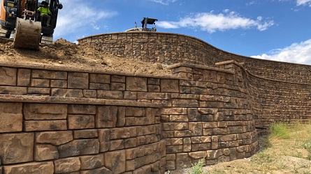
Many manufacturers offer various systems of stacked segmental concrete units, steel bins, or other devices that retain soil by stacking individual components. Most are patented systems that are typically battered (sloped backward), primarily to reduce lateral soil pressure, thus requiring a minimal foundation. Reinforced concrete footings, steel reinforcing, or mortar are not used. The stability of SRW gravity walls depends solely upon the dead weight resisting moment exceeding the lateral soil pressure overturning moment. To attain greater heights – up to 40 feet and more – SRW’s also utilizing mechanically stabilized earth (MSE), also called reinforced earth, whereby geosynthetic fabric layers are placed in successive horizontal layers of the backfill to achieve an integral soil mass that increases resistance to overturning and horizontal sliding. A variety of facing block configurations and surface colors and textures are available from many manufacturers.
9. Bridge Abutments
These support the end of a bridge and retain the earth embankment leading to the bridge. Bridge abutments usually have angled wing walls of descending height to accommodate the side slope of the embankment. Abutments are designed as cantilever walls, with girder bearing support free to slide at one end to accommodate horizontal expansion movement of the bridge deck. Design requirements for bridge structures are usually governed by the code requirements of the American Association of State Highway and Transportation Officials (AASHTO) and state Departments of Transportation (DOTs) such as California’s CalTrans.
10. Sheet Pile and Bulkhead Walls
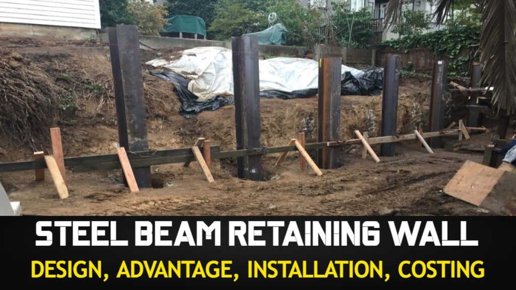
These are generally waterfront structures such as at docks and wharves, but steel sheet piling is also used for temporary shoring on construction sites. Steel sheet units configured for stiffness or concrete panels are driven into the soil to provide lateral support below the base of the excavation or the dredge line. Sheet pile walls cantilever upward to retain earth or are restrained at or near the top by either a slab-on-grade or tiebacks.
11. Restrained (Non-yielding) Retaining Walls
Also called “basement walls” (for residential and light commercial conditions) or “tie-back” walls. These walls are distinguished by having lateral support at or near the top, thereby with less or no dependence for fixity at the foundation. Technically, these walls are classified as “non-yielding” walls because the walls cannot move laterally at the top, as opposed to cantilevered (yielding) walls. Such walls are usually designed as “pin-connected” both at the top and bottom. The earth pressure creates a positive moment in the wall, which requires reinforcing on the front of the wall, that is, the side opposite the retained soil. In some cases, it may be cost-effective to fix the base of the wall to the footing to reduce both the bending in the wall and the restraining force required at the top support.
Footings for these walls are usually designed for vertical loads only. However, it is often desirable to design the lower portion of a basement wall as a cantilevered retaining wall with fixity at the footing so that backfill can be safely placed to avoid bracing the wall, or waiting until the lateral restraint at the top is in place, such as a floor diaphragm. Note that conventional wood floors framed into the top of a basement wall may not provide sufficient stiffness to allow for the restrained case,
12. Anchored (tieback) Walls
Anchors or tiebacks are often used for higher walls where a cantilevered wall may not be economical. Restraint is achieved by drilling holes and grouting inclined steel rods as anchors into the zone of earth behind the wall beyond the theoretical failure plane in the backfill. The anchors can be placed at several tiers for higher walls and can be post-tensioned rods grouted into drilled holes, or non-tensioned rods grouted into the drilled holes. The latter is also known as soil nails.
FEW TERMS & THEIR MEANING
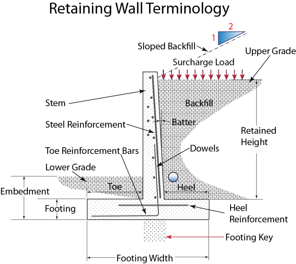
Backfill: The soil placed behind a wall.
Backfill slope: Often the backfill slopes upward from the back face of the wall. The slope is usually expressed as a ratio of horizontal to vertical (e.g. 2:1).
Batter: The slope of the face of the stem from a vertical plane, usually on the inside (earth) face.
Dowels: Reinforcing steel placed in the footing and bent up into the stem a distance at least equal to the required development length.
Footing (or foundation): That part of the structure below the stem that supports and transmits vertical and horizontal forces into the soil below.
Footing key: A deepened portion of the footing to provide greater sliding resistance.
Grade: The surface of the soil or paving; can refer to either side of the wall.
Heel: That portion of the footing extending behind the wall (under the retained soil).
Horizontal temperature/shrinkage reinforcing: Longitudinal horizontal reinforcing usually placed in both faces of the stem and used primarily to control cracking from shrinkage or temperature changes.
Keyway: A horizontal slot located at the base of the stem and cast into the footing for greater shear resistance.
Principal Reinforcing: Reinforcing used to resist bending in the stem.
Retained Height: The height of the earth to be retained, generally measured upward from the top of the footing.
Stem: The vertical wall above the foundation.
Surcharge: Any load placed in or on top of the soil, either in front or behind the wall.
Toe: That portion of footing which extends in front of the front face of the stem (away from the retained earth).
Weep Holes: Holes provided at the base of the stem for drainage. Weep holes usually have gravel or crushed rock behind the openings to act as a sieve and prevent clogging. Poor drainage of weep holes is the result of weep holes becoming clogged with weeds, thereby increasing the lateral pressure against the wall. Unless properly designed and maintained, weep holes seldom “weep”. Alternatively, a perforated pipe surrounded with gravel and encased within a geotextile can be used to provide drainage of the backfill.
Cantilevered Retaining Wall Terminology
Cantilevered retaining walls have unique descriptive terminology as illustrated below :
I hope you find this information useful. If there is something that I have missed or I do not know, you can comment and tell me which I will try to rectify as soon as possible.
If you have liked this post of mine, then use the social link given below and share it among your friends on social media. Thanks
Source – A Design Guide for Earth Retaining Structures By Hugh Brooks (Civil & Structural Engineer), John P. Nielsen (Civil & Geotechnical Engineer)
SHARE THIS POST, IF YOU LIKE IT !!
Padhega India Tab Hi Badhega India | पढ़ेगाइंडियातबहीबढ़ेगाइंडिया
